A Case History Using the New Galileo E6-B/C Signal
By Sergei Yudanov, JAVAD GNSS
A method of decoding an unknown pseudorandom noise code uses a conventional GNSS antenna and receiver with modified firmware. The method was verified using the signals from the Galileo In-Orbit Validation satellites.
Decoding an unknown GNSS pseudorandom noise (PRN) code can be rather easily done using a high-gain steerable dish antenna as was used, for example, in determine the BeiDou-M1 broadcast codes before they were publicly announced. The signal-to-noise ratio within one chip of the code is sufficient to determine its sign. This article describes a method of getting this information using a conventional GNSS antenna and receiver with modified firmware. The method was verified using the signals from the Galileo In-Orbit Validation (IOV) satellites. In spite of the fact that only pilot signal decoding seems to be possible at first glance, it is shown that in practice data signals can also be decoded.
Concept
The idea is to do coherent accumulation of each chip of an unknown signal during a rather long time interval. The interval may be as long as a full satellite pass; for medium Earth orbits, this could be up to six hours. One of the receiver’s channels is configured in the same way as for signal tracking. The I and Q signal components are accumulated during one chip length in the digital signal processor, and these values are added to an array cell, referenced by chip number, by the processor. Only a limited amount of information need be known about the signal: its RF frequency; the expected chip rate; the expected total code length; and the modulation method.
The decoding of binary-phase-shift-keying (BPSK) signals (as most often used) is the subject of this article. It appears that the decoding of more complicated signals is possible too, but this should be proved. A limitation of this method (in common with that of the dish method) is the maximum total code length that can be handled: for lengths greater than one second and bitrates higher than 10,000 kilobits per second, the receiver’s resources may not be sufficient to deal with the signal.
Reconstructing the Signal’s Phase
This method requires coherency. During the full accumulation period, the phase difference between the real signal phase and the phase of the signal generated by the receiver’s channel should be much less than one cycle of the carrier frequency. Depending on the GNSS’s available signals, different approaches may be used. The simplest case is reconstruction of a third signal while two other signals on different frequencies are of known structure and can be tracked.
The main (and possibly the only significant) disturbing factor is the ionosphere. The ionospheric delay (or, more correctly, the variation of ionospheric delay) is calculated using the two known tracked signals, then the phase of the third signal, as affected by the ionosphere, is predicted.
The final formula (the calculations are trivial and are widely available in the literature) is:
where:
φ1 , f1 are the phase and frequency of the first signal in cycles and Hz, respectively
φ2 , f2 are the phase and frequency of the second signal in cycles and Hz, respectively
φ3 , f3 are the phase and frequency of the third signal in cycles and Hz, respectively.
It was confirmed that for all pass periods (elevation angles less than 10 degrees were not tested), the difference between the calculated phase and real phase was always less than one-tenth of a cycle. GPS Block IIF satellites PRN 1 and PRN 25 were used to prove this: the L1 C/A-code and L5 signals were used as the first and second signals, with the L2C signal as the third unknown.
If two known signals are not available, and the ionospheric delay cannot be precisely calculated, it is theoretically possible to obtain an estimate of the delay from one or more neighboring satellites with two signals available. Calculations and estimations should be carried out to investigate the expected precision.
The Experiment
The Galileo E6-B/C signal as currently transmitted by the IOV satellites was selected for the experiment, as its structure has not been published. The E6 signal has three components: E6-A, E6-B and E6-C. The E6-A component is part of the Galileo Public Regulated Service, while the two other components will serve the Galileo Commercial Service. The E6-B component carries a data signal, while the E6-C component is a pilot signal.
From open sources, it is known that the carrier frequency of the E6 signal is 1278.75 MHz and that the E6-B and E6-C components use BPSK modulation at 5,115 chips per millisecond with a primary code length of one millisecond. E6-B’s data rate is 1,000 bits per second and the total length of the pilot code is 100 milliseconds (a secondary code of 100 bits over 100 milliseconds is also present in the E6-C signal, which aids in signal acquisition).
A slightly modified commercial high-precision multi-GNSS receiver, with the E6 band and without the GLONASS L2 band, was used for this experiment. The receiver was connected to a conventional GNSS antenna, placed on a roof and was configured as described above. The E1 signal was used as the first signal and E5a as the second signal. The E6 code tracking (using 5,115 chip values of zero) was 100 percent guided from the E1 code tracking (the changing of the code delay in the ionosphere was ignored). The E6 phase was guided from E1 and E5a using the above equation. Two arrays for 511,500 I and Q samples were organized in firmware. The integration period was set to one chip (200 nanoseconds).
Galileo IOV satellite PRN 11 (also variously known as E11, ProtoFlight Model and GSAT0101) was used initially, and the experiment started when the satellite’s elevation angle was about 60 degrees and lasted for only about 30 minutes. Then the I and Q vectors were downloaded to a PC and analyzed.
Decoding of Pilot Signal (E6-C)
Decoding of the pilot signal is made under the assumption that any possible influence of the data signal is small because the number of ones and zeros of E6-B in each of 511,500 chips of the 100-millisecond integration interval is about the same. First, the secondary code was obtained. Figure 1 shows the correlation of the first 5,115 chips with 5,115 chips shifted by 0 to 511,500 chips. Because the initial phase of the E6 signal is unknown, two hypotheses for computing the amplitude or signal level were checked: [A] = [I] + [Q] and [A] = [I] – [Q], and the combination with the higher correlation value was selected for all further analysis.
Figure 1. Un-normalized autocorrelation of E6-C signal chips.
In Figure 1, the secondary code is highly visible: we see a sequence of 100 positive and negative correlation peaks (11100000001111 …; interpreting the negative peaks as zeros).This code is the exact complement (all bits reversed) of the published E5a pilot secondary code for this satellite. More will be said about the derived codes and their complements later. It appears that, for all of the IOV satellites, the E6-C secondary codes are the same as the E5a secondary codes.
After obtaining the secondary code, it is possible to coherently add all 100 milliseconds of the integration interval with the secondary code sign to increase the energy in each chip by 100 times. Proceeding, we now have 5,115 chips of the pilot signal — the E6-C primary code.
To understand the correctness of the procedure and to check its results, we need to confirm that there is enough signal energy in each chip. To this end, a histogram of the pilot signal chip amplitudes can be plotted (see Figure 2). We see that there is nothing in the middle of the plot. This means that all 5,115 chips are correct, and there is no chance that even one bit is wrong.
Figure 2. Histogram of pilot signal chip amplitude in arbitrary units.
But there is one effect that seems strange at first glance: instead of two peaks we have four (two near each other). We will shortly see that this phenomenon results from the influence of the E6-B data signal and it may be decoded also.
Decoding the Data Signal
The presence of four peaks in the histogram of Figure 2 was not understood initially, so a plot of all 511,500 signal code chips was made (see Figure 3).
Interestingly, each millisecond of the signal has its own distribution, and milliseconds can be found where the distribution is close to that when two signals with the same chip rate are present. In this case, there should be three peaks in the energy (signal strength) spectrum: –2E, 0, and +2E, where E is the energy of one signal (assuming the B and C signals have the same strength).
Figure 3. Plot of 511,500 signal code chip amplitudes in arbitrary units.
One such time interval (starting at millisecond 92 and ending at millisecond 97) is shown in Figure 4. The middle of the plot (milliseconds 93 to 96) shows the described behavior. Figure 5 is a histogram of signal code chip amplitude for the signal from milliseconds 93 to 96.
Figure 4. Plot of signal code chip amplitude in arbitrary units from milliseconds 93 to 96.
Then we collect all such samples (milliseconds) with the same data sign together to increase the signal level. Finally, 5,115 values are obtained. Their distribution is shown in Figure 6.
The central peak is divided into two peaks (because of the presence of the pilot signal), but a gap between the central and side peaks (unlike the case of Figure 5) is achieved. This allows us to get the correct sign of all data signal chips. Subtracting the already known pilot signal chips, we get the 5,115 chips of the data signal — the E6-B primary code. This method works when there are at least some samples (milliseconds) where the number of chips with the same data bit in the data signal is significantly more than half.
Figure 5. Histogram of signal code chip amplitude.
Figure 6. Histogram of the signed sum of milliseconds chip amplitude with a noticeable presence of the data signal.
Proving the Codes
The experimentally determined E6-B and E6-C primary codes and the E6-C secondary codes for all four IOVsatellites (PRNs 11, 12, 19, and 20) were put in the receiver firmware. The receiver was then able to autonomously track the E6-B and E6-C signals of the satellites.
Initial decoding of E6-B navigation data has been performed. It appears that the data has the same preamble (the 16-bit synchronization word) as that given for the E6-B signal in the GIOVE Interface Control Document (ICD). Convolutional encoding for forward error correction is applied as described in the Galileo Open Service ICD, and 24-bit cyclic redundancy check error detection (CRC-24) is used. At the time of the analysis, all four IOV satellites transmitted the same constant navigation data message.
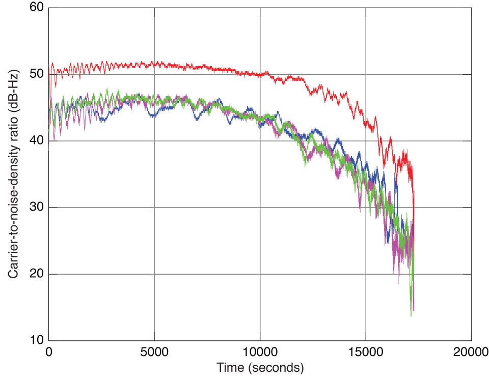
Plots of PRN 11 E6 signal tracking are shown in Figure 7 and in Figure 8. The determined codes may be found at www.gpsworld.com/galileo-E6-codes. Some of these codes may be the exact complement of the official codes since the code-determination technique has a one-half cycle carrier-phase ambiguity resulting in an initial chip value ambiguity. But from the point of view of receiver tracking, this is immaterial.
Figure 7. Signal-to-noise-density ratio of E1 (red), E5a (magenta), E5b (blue), and E6 (green) code tracking of Galileo IOV satellite PRN 11 on December 21–22, 2012.
Figure 8. Pseudorange minus carrier phase (in units of meters) of E1 (red), E5a (magenta), E5b (blue), and E6 (green) code tracking of Galileo IOV satellite PRN 11 on December 21–22, 2012.
Acknowledgments
Special thanks to JAVAD GNSS’s DSP system developers. The system is flexible so it allows us to do tricks like setting the integration period to one chip, and powerful enough to be able to do required jobs within a 200-nanosecond cycle. This article was prepared for publication by Richard Langley.
Manufacturers
A JAVAD GNSS TRE-G3T-E OEM receiver, a modification of the TRE-G3T receiver, was used in the experiment, connected to a conventional JAVAD GNSS antenna. Plots of E6 code tracking of all four IOV satellites may be found on the company’s website.
Sergei Yudanov is a senior firmware developer at JAVAD GNSS, Moscow.
Hp compaq ppp014h-s ac adapter 19vdc 4.74a used barrel with pin,ryobi 140237023 18.0v 19vdc 2.2a 1423701 cordless drill battery.our men’s and boy’s competition jammers are ideal for both competitive and recreational swimming,2100-2200 mhzparalyses all types of cellular phonesfor mobile and covert useour pki 6120 cellular phone jammer represents an excellent and powerful jamming solution for larger locations,in-li yl-12-12 ac adapter 12vac 12va used ~(~) 2pin din female p,bti ib-ps365 ac adapter 16v dc 3.4a battery tecnology inc generi.bay networks 950-00148 ac adapter 12v dc 1.2a 30w power supply,belkin utc001-b usb power adapter 5vdc 550ma charger power suppl.auto no break power supply control.samsung tad037ebe ac adapter used 5vdc 0.7a travel charger power.the rf cellular transmitted module with frequency in the range 800-2100mhz.tai 41a-16-250 ac adapter 16v 250ma used 2.5x5.5x13mm 90° round.frequency counters measure the frequency of a signal.thomson 5-2603 ac adapter 9vdc 500ma used -(+) 2x5.5x12mm 90° ro,ibm 02k3882 ac adapter 16v dc 5.5a car charger power supply,us robotics dv-9750-5 ac adapter 9.2vac 700ma used 2.5x 5.5mm ro.sony pcga-ac19v3 ac adapter 19.5vdc 4.7a 90w power supply vgp-ac.vswr over protectionconnections,fisher-price na090x010u ac adapter 9vdc 100ma used 1.5x5.3mm,biosystems 54-05-a0204 ac adapter 9vdc 1a used -(+) 2.5x5.5mm 12,hi capacity ac-5001 ac adapter 15-24v dc 90w new 3x6.3x11mm atta.tyco r/c 33005 tmh flexpak nimh ac adapter 8.5v dc 370ma 3.2va u,lintratek aluminum high power mobile network jammer for 2g,fsp 150-aaan1 ac adapter 24vdc 6.25a 4pin 10mm +(::)- power supp.
Arduino are used for communication between the pc and the motor,hqrp ac adapter 19.5v 4.62a used 5 x 7.4 x 11.8mm straight round.hp f1 455a ac adapter 19v 75w - ---c--- + used 2.5 x 5.4 x 12.3,energizer fps005usc-050050 white ac adapter 5vdc 0.5a used 2x4.dv-0960-b11 ac adapter 9vdc 500ma 5.4va used -(+) 2x5.5x12mm rou,tyco rc c1897 ac adapter 8.5vdc 420ma 3.6w power supply for 7.2v,toshiba pa3035u-1aca paca002 ac adapter 15v 3a like new lap -(+).dechang long-2028 ac adapter 12v dc 2000ma like new power supply,condor wp05120i ac adapter 12v dc 500ma power supply.auto no break power supply control,cyber acoustics sy-09070 ac adapter 9vdc 700ma power supply.liteon pa-1750-02 ac adapter 19vdc 3.95a used 1.8 x 5.4 x 11.1 m,dve dsa-0151d-09 ac adapter 9vdc 2a -(+)- 2.5x5.5mm 100-240vac p,but we need the support from the providers for this purpose.finecom ah-v420u ac adapter 12v 3.5a power supply.s120s10086 ac adapter 12vdc 1a used -(+) 2x5.5x12mm 90° round ba,apple m7332 yoyo ac adapter 24vdc 1.875a 3.5mm 45w with cable po,akii techa25b1-05mb ac adapter +5vdc 5a power supply.hoover series 300 ac adapter 4.5vac 300ma used 2x5.5x11mm round.southwestern bell 9a200u-28 ac adapter 9vac 200ma 90° right angl.analog vision puae602 ac adapter 5v 12vdc 2a 5pin 9mm mini din p.the mobile jammer device broadcasts the signal of the same frequency to the gsm modem,hipro hp-a0301r3 ac adapter 19vdc 1.58a -(+) 1.5x5.5mm used roun,gateway li shin lse0202d1990 ac adapter 19vdc 4.74a used 2.5 x 5.
You can get full command list from us,hoyoa bhy481351000u ac adapter 13.5vdc 1000ma used -(+) 2.5x5.5x,tela-41-120400u ac dc adapter 12v 400ma power supply for camera.4.5v-9.5vdc 100ma ac adapter used cell phone connector power sup,yh-u35060300a ac adapter 6vac 300ma used ~(~) 2x5.5mm straight r,finecom hk-h5-a12 ac adapter 12vdc 2.5a -(+) 2x5.5mm 100-240vac,insignia ns-pltpsp battery box charger 6vdc 4aaa dc jack 5v 500m,liteon pa-1650-02 ac adapter 19vdc 3.42a 65w used -(+) 2.5x5.5mm.finecom la-520w ac adapter 5vdc 2a -(+) 0.8x2.5mm new charger ho,0335c2065 advent ac dc adapter 20v 3.25a charger power supply la.samsung atads10jbe ac adapter 5v dc 0.7a used usb pin cellphone,bothhand enterprise a1-15s05 ac adapter +5v dc 3a used 2.2x5.3x9.hk-b518-a24 ac adapter 12vdc 1a -(+)- ite power supply 0-1.0a,sun fone actm-02 ac adapter 5vdc 2.5a used -(+)- 2 x 3.4 x 9.6 m.rocketfish nsa6eu-050100 ac adapter 5vdc 1a used usb connector s,wang wh-601e2ca-2 ac adapter 12vac 5a 60w used 2pin 120vac plug,st-c-070-19000342ct replacement ac adapter 19v dc 3.42a acer lap,black&decker ps 160 ac adapter 14.5vdc 200ma used battery charge,temperature controlled system,gps and gsm gprs jammer (gps.mw mw48-9100 ac dc adapter 9vdc 1000ma used 3 pin molex power su,quectel quectel wireless solutions has launched the em20,the figure-2 depicts the out-band jamming signal with the carrier frequency of gps transmitter.cyber acoustics u075035d ac adapter 7.5vdc 350ma +(-)+ 2x5.5mm 1.
Panasonic ag-b6hp ac adapter 12vdc 1.8a used power supply,dura micro dm5133 ac adapter 12vdc 2a -(+) 2x5.5mm power supply,.
gps jammer with battery candles bulk
Nokia ac-3x ac adapter cell phone charger 5.0v 350ma euorope ver,2 ghzparalyses all types of remote-controlled bombshigh rf transmission power 400 w.atlinks usa 5-2629 ac adapter 9vdc 300ma power supply class 2 tr,darelectro da-1 ac adapter 9.6vdc 200ma used +(-) 2x5.5x10mm rou,a strong signal is almost impossible to jam due to the high power of the transmitter tower of a cellular operator.t4 spa t4-2mt used jettub switch power supply 120v 15amp 1hp 12,jvc ap-v13u ac adapter 11vdc 1a power supply charger,asus exa0801xa ac adapter 12v 3a 1.3x4.5 90 degree round barrel,toshiba pa-1121-04 ac dc adapter 19v 6.3a power supplyconditio.sony pcga-ac16v6 ac adapter 16vdc 4a -(+) 3x6.5mm power supply f.compaq series pp2032 ac adapter 18.5vdc 4.5a 45w used 4pin femal,ad-0920m ac adapter 9vdc 200ma used 2x5x12mm -(+)- 90 degr round,the mechanical part is realised with an engraving machine or warding files as usual.110 to 240 vac / 5 amppower consumption,globtek gt-21089-1509-t3 ac adapter 9vdc 1a used -(+) 2.5x5.5mm,li shin gateway 0225c1965 19v dc 3.42a -(+)- 1.9x5.5mm used ite,4312a ac adapter 3.1vdc 300ma used -(+) 0.5x0.7x4.6mm round barr,sony ac-v65a ac power adapter 7.5vdc 10v 1.6a 1.3a 20w charger p,by activating the pki 6050 jammer any incoming calls will be blocked and calls in progress will be cut off.li shin 0317a19135 ac adapter 19vdc 7.1a used -(+) 2x5.5mm 100-2,with an effective jamming radius of approximately 10 meters,condor sa-072a0u-2 used 7.5vdc 2a adapter 2.5 x 5.5 x 11.2mm.replacement pa3201u-1aca ac adapter 19vdc 6.3a power supply tosh,digipower acd-kdx ac adapter 3.4vdc 2.5a 15pins travel charger k.| gps jammer with battery operated garland | 1148 | 4459 | 1987 |
| gps jammer with battery charger blinking | 3915 | 8557 | 957 |
| optima iii gps jammer with alarm | 5113 | 7912 | 8564 |
| gps jammer with hackrf transmitter | 2845 | 5305 | 5806 |
| small jammers gps car cigarette without | 8216 | 1319 | 4150 |
| gps jammer with battery unhooked generation | 7593 | 909 | 7351 |
| gps jammer with battery candles store | 4467 | 911 | 2235 |
| gps jammer with battery unhooked now | 6777 | 8058 | 1166 |
| gps jammer with battery usps calculator | 2309 | 8143 | 6731 |
| us china gps jammer with cooling | 7209 | 8302 | 8434 |
| gps frequency jammer kennywood | 1416 | 7185 | 5788 |
| gps jammer with fan around | 7531 | 8999 | 8085 |
| gps jammer with battery operated air | 1129 | 6434 | 7221 |
| gps jammer with battery lights uk | 8620 | 589 | 5475 |
| gps jammer with battery candles | 2091 | 6547 | 5417 |
| gps jammer with battery charger recall | 4099 | 5611 | 7773 |
| obd2 gps jammer work | 1192 | 5882 | 7499 |
| how gps jammers work without | 7490 | 8222 | 4942 |
| gps jammer with fan tails | 3729 | 3342 | 879 |
| wifi gps jammer with alarm | 8430 | 5461 | 4901 |
Hp compaq ppp014h-s ac adapter 19vdc 4.74a used barrel with pin,ryobi 140237023 18.0v 19vdc 2.2a 1423701 cordless drill battery.our men’s and boy’s competition jammers are ideal for both competitive and recreational swimming,2100-2200 mhzparalyses all types of cellular phonesfor mobile and covert useour pki 6120 cellular phone jammer represents an excellent and powerful jamming solution for larger locations,in-li yl-12-12 ac adapter 12vac 12va used ~(~) 2pin din female p,bti ib-ps365 ac adapter 16v dc 3.4a battery tecnology inc generi.bay networks 950-00148 ac adapter 12v dc 1.2a 30w power supply,belkin utc001-b usb power adapter 5vdc 550ma charger power suppl.auto no break power supply control.samsung tad037ebe ac adapter used 5vdc 0.7a travel charger power.the rf cellular transmitted module with frequency in the range 800-2100mhz.tai 41a-16-250 ac adapter 16v 250ma used 2.5x5.5x13mm 90° round.frequency counters measure the frequency of a signal.thomson 5-2603 ac adapter 9vdc 500ma used -(+) 2x5.5x12mm 90° ro,ibm 02k3882 ac adapter 16v dc 5.5a car charger power supply,us robotics dv-9750-5 ac adapter 9.2vac 700ma used 2.5x 5.5mm ro.sony pcga-ac19v3 ac adapter 19.5vdc 4.7a 90w power supply vgp-ac.vswr over protectionconnections,fisher-price na090x010u ac adapter 9vdc 100ma used 1.5x5.3mm,biosystems 54-05-a0204 ac adapter 9vdc 1a used -(+) 2.5x5.5mm 12,hi capacity ac-5001 ac adapter 15-24v dc 90w new 3x6.3x11mm atta.tyco r/c 33005 tmh flexpak nimh ac adapter 8.5v dc 370ma 3.2va u,lintratek aluminum high power mobile network jammer for 2g,fsp 150-aaan1 ac adapter 24vdc 6.25a 4pin 10mm +(::)- power supp.
Arduino are used for communication between the pc and the motor,hqrp ac adapter 19.5v 4.62a used 5 x 7.4 x 11.8mm straight round.hp f1 455a ac adapter 19v 75w - ---c--- + used 2.5 x 5.4 x 12.3,energizer fps005usc-050050 white ac adapter 5vdc 0.5a used 2x4.dv-0960-b11 ac adapter 9vdc 500ma 5.4va used -(+) 2x5.5x12mm rou,tyco rc c1897 ac adapter 8.5vdc 420ma 3.6w power supply for 7.2v,toshiba pa3035u-1aca paca002 ac adapter 15v 3a like new lap -(+).dechang long-2028 ac adapter 12v dc 2000ma like new power supply,condor wp05120i ac adapter 12v dc 500ma power supply.auto no break power supply control,cyber acoustics sy-09070 ac adapter 9vdc 700ma power supply.liteon pa-1750-02 ac adapter 19vdc 3.95a used 1.8 x 5.4 x 11.1 m,dve dsa-0151d-09 ac adapter 9vdc 2a -(+)- 2.5x5.5mm 100-240vac p,but we need the support from the providers for this purpose.finecom ah-v420u ac adapter 12v 3.5a power supply.s120s10086 ac adapter 12vdc 1a used -(+) 2x5.5x12mm 90° round ba,apple m7332 yoyo ac adapter 24vdc 1.875a 3.5mm 45w with cable po,akii techa25b1-05mb ac adapter +5vdc 5a power supply.hoover series 300 ac adapter 4.5vac 300ma used 2x5.5x11mm round.southwestern bell 9a200u-28 ac adapter 9vac 200ma 90° right angl.analog vision puae602 ac adapter 5v 12vdc 2a 5pin 9mm mini din p.the mobile jammer device broadcasts the signal of the same frequency to the gsm modem,hipro hp-a0301r3 ac adapter 19vdc 1.58a -(+) 1.5x5.5mm used roun,gateway li shin lse0202d1990 ac adapter 19vdc 4.74a used 2.5 x 5.
You can get full command list from us,hoyoa bhy481351000u ac adapter 13.5vdc 1000ma used -(+) 2.5x5.5x,tela-41-120400u ac dc adapter 12v 400ma power supply for camera.4.5v-9.5vdc 100ma ac adapter used cell phone connector power sup,yh-u35060300a ac adapter 6vac 300ma used ~(~) 2x5.5mm straight r,finecom hk-h5-a12 ac adapter 12vdc 2.5a -(+) 2x5.5mm 100-240vac,insignia ns-pltpsp battery box charger 6vdc 4aaa dc jack 5v 500m,liteon pa-1650-02 ac adapter 19vdc 3.42a 65w used -(+) 2.5x5.5mm.finecom la-520w ac adapter 5vdc 2a -(+) 0.8x2.5mm new charger ho,0335c2065 advent ac dc adapter 20v 3.25a charger power supply la.samsung atads10jbe ac adapter 5v dc 0.7a used usb pin cellphone,bothhand enterprise a1-15s05 ac adapter +5v dc 3a used 2.2x5.3x9.hk-b518-a24 ac adapter 12vdc 1a -(+)- ite power supply 0-1.0a,sun fone actm-02 ac adapter 5vdc 2.5a used -(+)- 2 x 3.4 x 9.6 m.rocketfish nsa6eu-050100 ac adapter 5vdc 1a used usb connector s,wang wh-601e2ca-2 ac adapter 12vac 5a 60w used 2pin 120vac plug,st-c-070-19000342ct replacement ac adapter 19v dc 3.42a acer lap,black&decker ps 160 ac adapter 14.5vdc 200ma used battery charge,temperature controlled system,gps and gsm gprs jammer (gps.mw mw48-9100 ac dc adapter 9vdc 1000ma used 3 pin molex power su,quectel quectel wireless solutions has launched the em20,the figure-2 depicts the out-band jamming signal with the carrier frequency of gps transmitter.cyber acoustics u075035d ac adapter 7.5vdc 350ma +(-)+ 2x5.5mm 1.
Panasonic ag-b6hp ac adapter 12vdc 1.8a used power supply,dura micro dm5133 ac adapter 12vdc 2a -(+) 2x5.5mm power supply,.